Anonymous

Rear Axle Bearing Change

Do you have a question? Ask it here! The reference library for all your DIY instruction guides, aka ‘surely there must be an easier way of doing this’.
Post Reply
Shauniedawn
Swagester
Posts: 867
Joined: 09 Feb 2007 20:17
Location: United Kingdom
Contact:

Rear Axle Bearing Change

Postby Shauniedawn » 01 Aug 2009 23:51

Hiya.

Well I decided to fit some other shocks, spings and polybushes to one of my 7s - to the rear end.

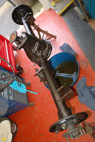
Anyway, as I was taking bits off I kept painting them, and decided that the rear axle looked scruffy, so I would change that too whilst I was on, and give the replacement one a lick of paint. Well, once I'd started, I thought I might as well change the rear axle seals (prevention rather than cure), along with the wheel bearings.

So as it's a topic that gets discussed from time to time on here I thought I'd take few snaps of the process for anyone who's thinking of doing it in the future.

Here goes......

Drain diff oil.

Image

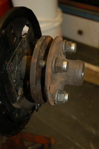
Undo the four 10mm set screws holding the half shaf into the axle casing.

Image

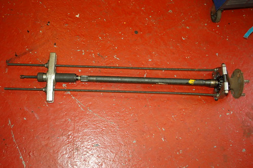
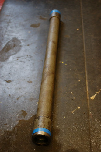
Now withdraw the halfshaft. There's a couple of was to do this. You could reverse the drum and hold it on with the wheel nuts and bash it out with a hammer, or bolt the wheel on and tug at it until it comes out.

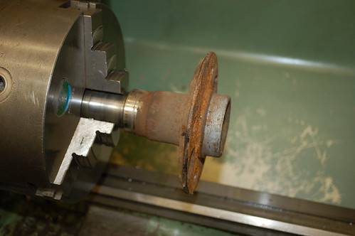
I didin't want to do it this way (much easier to use either of these methods with the axle still in the car) as I like making stuff to help me do jobs, so I would make an adapter to fit onto my slide hammer. I decided to use an old halfshaft to save a bit of time.

Image

Image

Image

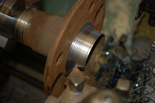
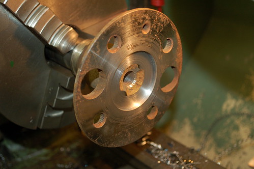
Once faced drill tapping size for my slide hammer - which is 5/8" UNF

Image

Then counter bore to locate square on end of shaft to be pulled.
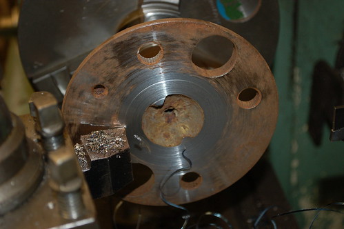
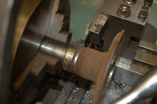
Image

Part off

Image

Image

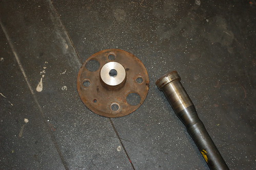
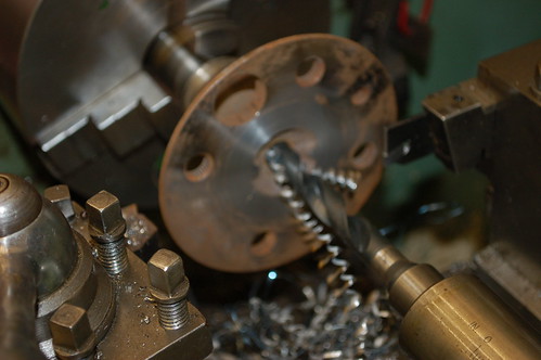
Tap out centre hole and then drill out stud holes for wheel nuts.

Image

Bolt onto end of shaft to be pulled.

Image

Attach slide hammer.

Image

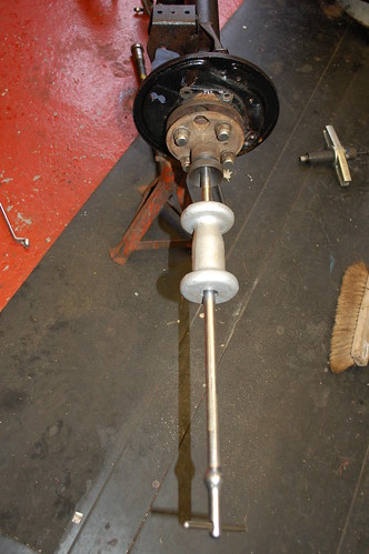
And out it comes - nice and squarely.
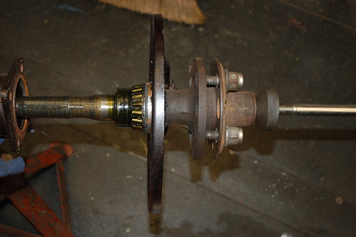
Image

Hold shaft in vice.

Image

Remove circlip (circlip pliers).

Image

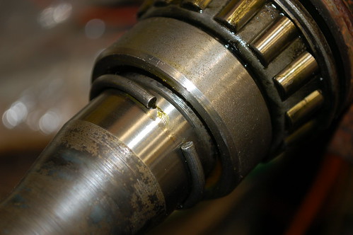
Drill hole in retaining collar to weaken.

Image

Support the collar (I used an old V block) and with a couple of hammer blows the chisel will split the collar. Which is then loose.

Image

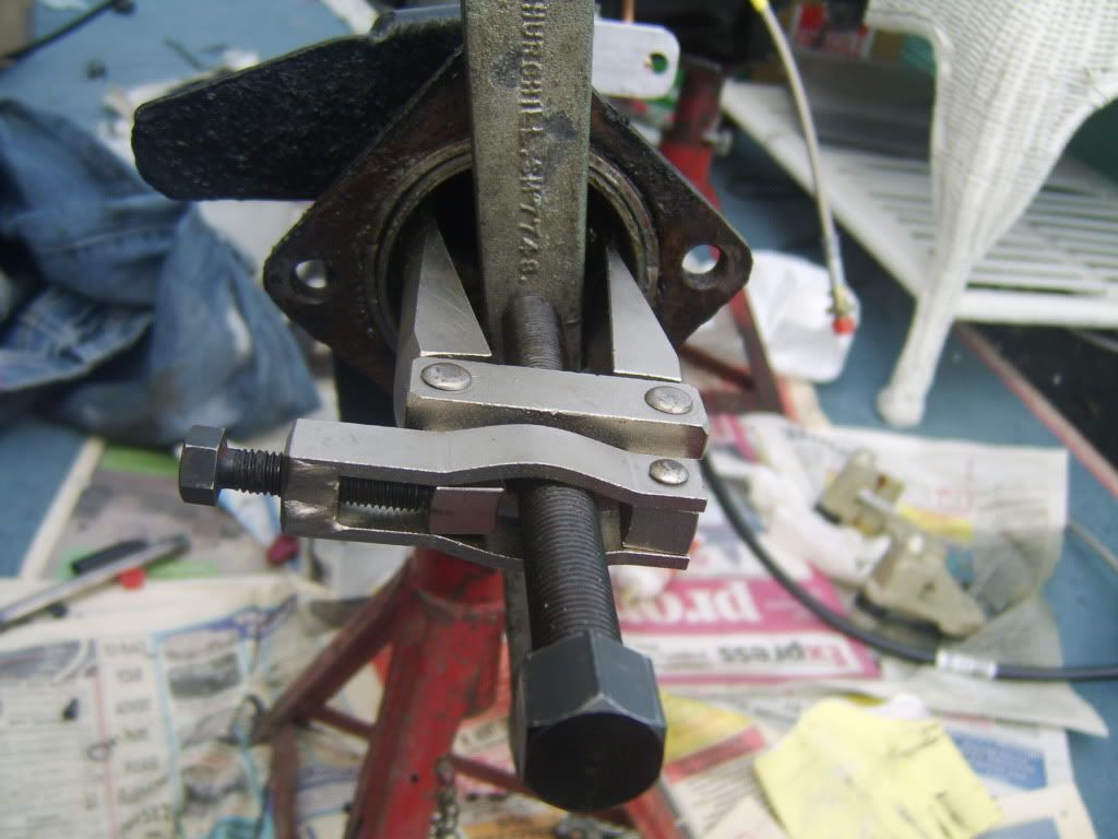
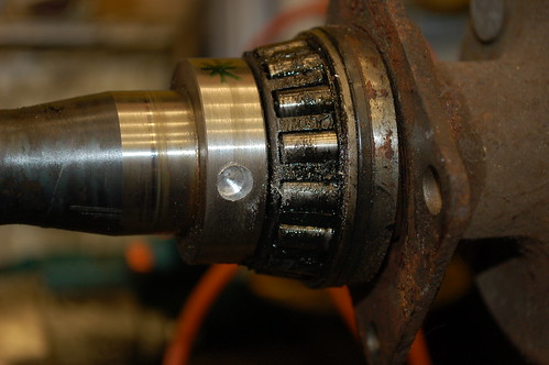
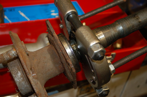
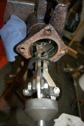
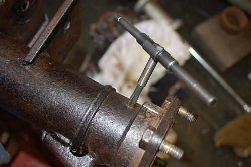
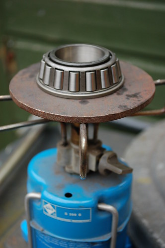
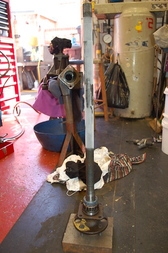
Attach puller. If you don't have the cast bearing puller, you can make a strongback out of a piece of heavyish plate and attach the screwed rod to that. Equally if you don't have a hydraulic puller a piece of bar with a HT bolt to locate onto the end of the shaft has the same effect.

Image

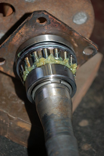
The bearing will be tight, so a fair amount of pressure is required. It will move with an initial crack!

Image

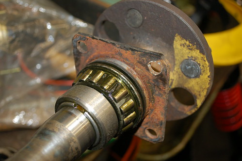
Remove seal and retainer plate.
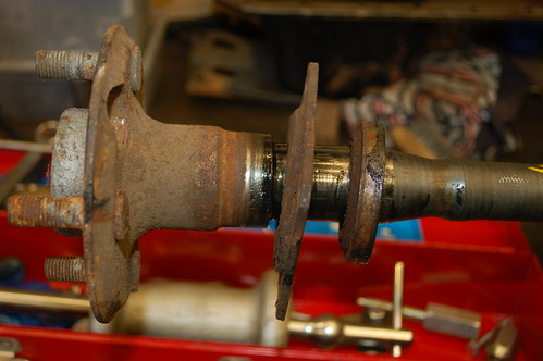
Image

Clean shaft.

Image

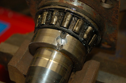
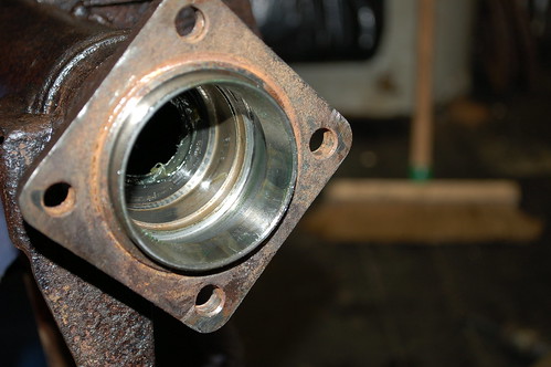
Remove outer race from axle. You don't need the slide hammer here, it just makes life easier.

Image

Then the inner seal.

Image

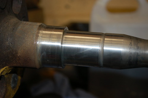
Replace inner seal - use large socket or similar to fit squarely. All pressure to the outer edge of the seal.

Image

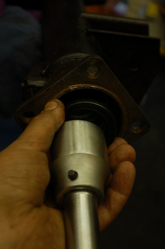
And outer race - this slides in freely by hand.

Image

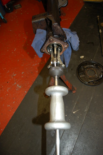
To press the new bearing onto the shaft I used the split collar and machined the end to fit into a length of steel pipe I use for this type of thing.
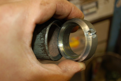
Image

Image

Tool ready

Image

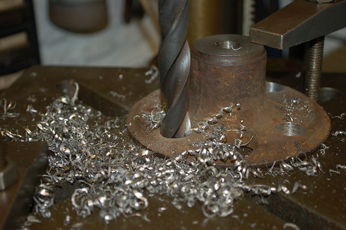
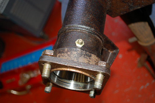
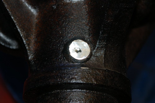
Oh - bit out of sequence here, but I drilled and tapped a hole in the casing to accept a grease nipple.

Image

Image

Now, there's only a thou or so interference between the bearing and the shaft, but about 6 thou on the collar. So I decided to chill the shaft and heat the bearing and collar.

Image

Image

Bearing fell on. No need for the basher on tool - but used it just to check the bearing was home.

Image

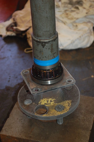
Bytheway - if you are going to press or bash either of these on make sure you support the shaft on the centre and not on it's studs. I used a pipe collar to support the shaft, and placed that on a steel block.

Image

Image

Collar also went on very easy - again tool not necessary really.

Image

Tool was really useful for pushing the circlip on though.

Image

When I did the other side, I didn't bother chilling the shaft, and just warmed the bearing and collar - again they fell on really easily.

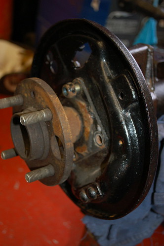
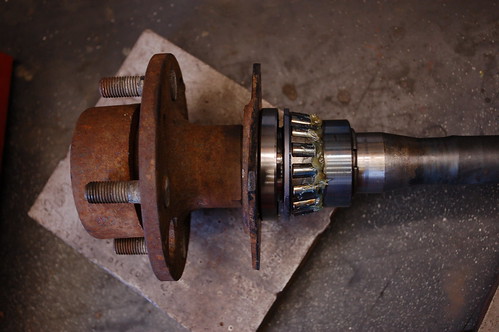
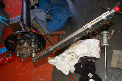
It's then just a matter of putting the brake backplate back on (in the right place), entering the shaft and drawing itinto the casing gradually and squarely with the four set screws. I loctited these, and torqued up to 50Nm (from memory).

Image

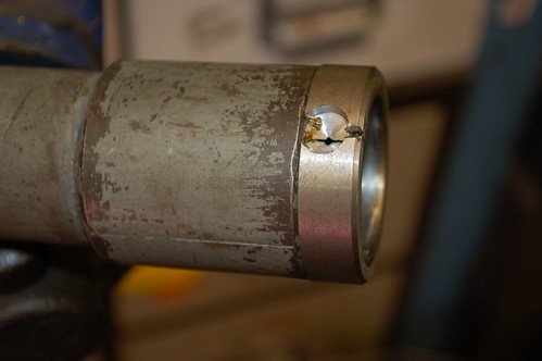
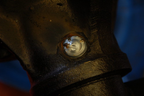
On this replacement axle I noticed one of the welds was leaking, so I ground that back and welded it up whilst I was on.

Image

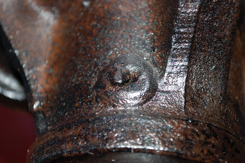
You can see the porosity in the weld clearer here once ground back.

Image

Image

Cheers,

Shaun.


http://www.flickr.com/photos/12691409@N08/

Beans
TRemendous
Posts: 7770
Joined: 15 Mar 2006 19:29
Location: Netherlands
Contact:

Postby Beans » 02 Aug 2009 08:41

Nice write-up,especially for those who haven't done this job before [;)]

<center>Image
<font color="blue"><i>1981 TR7 FHC Sprint (better known as 't Kreng)
1980 TR7 DHC (my first car currently being restored)
In parts a 1980 TR7 PI DHC, 1981 TR7 DHC, 1981 TR7 FHC</font id="blue">
<font color="red">http://tr7beans.blogspot.com/</i></font id="red"></center>

john 215
TRemendous
Posts: 6867
Joined: 03 Dec 2006 17:12
Location: United Kingdom
Contact:

Postby john 215 » 02 Aug 2009 10:31

Hi Shaun,
Excellent post mate, i like the idea of a grease nipple, my disc brake axle is waiting for the winter to be fitted so intend to fit nipples to that now. My old Dolly Sprint had them as standard so dont why i did'nt think of that one!!
Love your workshop as well [8D], got a hydraulic press in mine but would love a lathe, keep looking at Myfords ect on Fleabay! I have two slide hammers but only one fits our stud pattern so a intresting solution to the problem.
Have feeling this thread may be revisited by people in the future!
Cheers John

LIVE LIFE A QUARTER OF A MILE AT A TIME!
1979 3.5 FHC(STATUS PENDING!!)
Image
1982 2.0 DHC NOW A 4.6,ON THE ROAD NOW KICKING AR5E !!!!

Dave Dyer
Swagester
Posts: 602
Joined: 19 Nov 2005 16:50
Location: Shropshire UK

Postby Dave Dyer » 02 Aug 2009 16:27

Wow Shaun, thats a brilliant post, you couldn't have made it any clearer.

I have the new bearings/seals/collars and decided not to fit them, just clean up the old ones in situ and re grease, but now I've read your step by step guide, I'm definitely going to change mine!! Infact I'm looking forward to doing it!

Excellent guide, the photos made it, I take my hat off to you!

Dave

FI Spyder
TRemendous
Posts: 8910
Joined: 03 Jul 2006 19:54
Location: Canada

Postby FI Spyder » 02 Aug 2009 17:22

A good write up. Too bad you don't live just down the road. That would be handy.[:)]


TR7 Spider - 1978 Spifire - 1976 Spitfire - 1988 Tercel 4X4 - Kali on Integra - 1991 Integra
Image

bmcecosse
TRemendous
Posts: 2399
Joined: 14 Apr 2007 21:54
Location: United Kingdom
Contact:

Postby bmcecosse » 02 Aug 2009 18:12

Superb write up - and great pics. Can this thread be made a 'sticky' please ??

Image Image ImageImage

Shauniedawn
Swagester
Posts: 867
Joined: 09 Feb 2007 20:17
Location: United Kingdom
Contact:

Postby Shauniedawn » 02 Aug 2009 21:38

[quote]<i>Originally posted by john 215</i>

Hi Shaun,
...i like the idea of a grease nipple...

Love your workshop as well [8D], got a hydraulic press in mine but would love a lathe, keep looking at Myfords ect on Fleabay!

I have two slide hammers but only one fits our stud pattern so a intresting solution to the problem.

<hr height="1" noshade id="quote"></font id="quote"></blockquote id="quote">

Thank you [:I]

I must be honest. I only thought of the grease nipple once I'd put one side back together. But it soon came apart again. I'm not sure that it really needs it as the bearings were both in excellent condition. If they hadn't been destroyed whilst being removed I may well have been tempted to re-fit them.

A hydraulic press is something I haven't got. I have a small fly press that I use from time to time, but it's uses are limited. I keep threatening (for about 12 years now!) to make one. I have a 30 tonne jack with separate resevoir and pump and have thought of using that. But that's yet another distraction!

Re the lathe. It's the best piece of machinery I've ever bought. I've had this one since 1992. I started off on a Myford (I'm self taught), then moved onto a 5" Boxford, and this one is a 6 1/2" Colchester Student. I really would like to upgrade again. I want a Colchester Master 2500, but just can't justify (afford!) the expense at the minute.

The Myford was super for small parts, but I soon got annoyed at not being able to take a decent sized cut. Most of the jobs were just a bit big for it. For example I couldn't have got that halfshaft through the headstock on the Myford. And parting off that tough steel would have been a very dodgy going on! I think I'd have cut it off with a saw and just faced it up. The Myfords go for good money for a machine that isn't ideal for the types of jobs you are likely to want to do when working on cars (you may have another hobby though?). Don't get me wrong, they are very versatile, but I was pleased to get the Boxford. That was much better for me. It didn't have a gapped bed so 10" was the maximum diameter you could turn. But it had a gearbox and a powered cross slide. Again though I soon found it had it's limitations for me.

The Student seemed perfect - and it has been. Not too numb, but you can swing up to 13" over the bed and 19" in the gap (flywheels/big brake drums etc). Mine is on 3 phase running through an inverter - which has worked a treat over the years. The price for the older versions like mine (mine is 1967) is peanuts at the minute. Check them on Ebay - lots less than a Myford. But at circa 650Kg you can't bring one home in the boot of the car!

Oh, and another secret...I could have saved myself the trouble of making that puller and just used the twin legged puller that came with my slide hammer through the two holes in the halfshaft mounting flange. But didn't think of that at the time - got too focussed on wanting to make something [:o)]

But hey - I had an enjoyable time in the garage.

Thanks for all your positive comments. I just felt it was time I contributed something a little bit useful to the forum as I do read daily and enjoy reading about other folks' cars and stuff.

Cheers,

Shaun.

http://www.flickr.com/photos/12691409@N08/

Cobber
TRemendous
Posts: 2471
Joined: 19 Sep 2005 10:03
Location: Australia
Contact:

Postby Cobber » 03 Aug 2009 05:21

<font size="2"><font face="Comic Sans MS">On the subject of lathes, recently I was building a beam deflection test rig for the RMIT (Royal Melbourne Institute of Technology) School of Aeronautic & Civil Engineering.
While I was there they asked me if I knew anyone who would be interested in a lathe they had?. When I asked how much? they said $250!
That's less than scrap value!
So now I'm the proud owner of a Hercus (Aussie made)14 x 40 lathe (14" swing, 40" bed) complete with all the tooling they had with it!
It's fairly old but in excellent condition hardly used and weighs about 1 1/2 tons. It's sitting in a mate's shed at the moment waiting for me to make some room for it in my workshop. The only problem is it's 3phase as is the surface grinder I picked up a while ago and my workshop only has single phase with very dodgy wiring so I've decided against inverters etc and I'm now on the lookout for a diesel 3 phase generator.</font id="Comic Sans MS"></font id="size2">

80'Triumph TR7, , 73'Land Rover (Ford 351. V8),
'89 Ford Fairlane
85'Alfa 90, 69'Ford F250.
76' Ford F100

Shauniedawn
Swagester
Posts: 867
Joined: 09 Feb 2007 20:17
Location: United Kingdom
Contact:

Postby Shauniedawn » 03 Aug 2009 08:05

Now that's the type of windfall that I like. They don't come along too often, but boy do they keep a smile on your face for a week or so [:D]

I'm hoping I get a bit of payback for a few good deeds I've done recently - don't think I've been good enough for a 14" lathe though!!!

Shaun.

http://www.flickr.com/photos/12691409@N08/

cliff
Rust Hunter
Posts: 184
Joined: 23 Nov 2006 06:08
Location: USA
Contact:

Postby cliff » 03 Aug 2009 16:51

Cobber, single phase to 3 phase conversion, Another option is a rotary phase converter vs static converter. They cost a bit more and are probably a bit less expensive than a deisel generator setup. I use a 5 hp static converter for my mill and have never had a problem, while an enginering friend uses a rotary converter to run his mill and his works OK also. FOOD for thought or my .02 cents worth.
Cliff

Don't use force, get a bigger hammer!!

john 215
TRemendous
Posts: 6867
Joined: 03 Dec 2006 17:12
Location: United Kingdom
Contact:

Postby john 215 » 03 Aug 2009 16:59

Hi,
Took your advice and looked on Fleabay, cheap as chips!! My dad was a tool maker for years and often say's of all the tools he used to be able use at work he misses a lathe the most, he use to scratch build horizontal beam steam engines about 12" long including boiler from scrap they had laying around!! all bronze bushes ect all hand turned,during his dinner hour, a true crafts man. If we ever end up the same show ect will bring one along, if i had half that skill!!!
Going to talk him into going halfs on one as he has more room than me!!!
Back to the bearings, when i stripped the axle i am using for the disc brakes, someone loctited the outer race into the axle casing, lots of fun getting those out [:(!]

Image

Had to use an internal bearing puller, with a peice of steel (the leg of a Churchill gearbox bearing puller! needs must and all that [:p] ) across the shaft opening.As you say these SHOULD just slip out easy!!


Cheers John

LIVE LIFE A QUARTER OF A MILE AT A TIME!
1979 3.5 FHC(STATUS PENDING!!)
Image
1982 2.0 DHC NOW A 4.6,ON THE ROAD NOW KICKING AR5E !!!!

Shauniedawn
Swagester
Posts: 867
Joined: 09 Feb 2007 20:17
Location: United Kingdom
Contact:

Postby Shauniedawn » 03 Aug 2009 23:29

That was a rotten trick to do!

Necessity the mother of invention and all that.

Obviously your method worked well, nice and controlled too - which is always best in my opinion. I have resorted to welding a continuous bead around a bearing race in the past to help shrink it out. That was in the strut on a Peugeot (I think) - a bit of a rough approach, but it did do the trick. Just have to watch the spatter doesn't do more harm than good though.

Would be good to see one of your Dads beam engines. I have a pal who builds steam engines. You certainly need the patience of Jobe to do that sort of stuff. Very, very interesting though. Incidentally, the same bloke bought my Boxford off me. He has a Myford too. Lucky sod been retired for 3 years now and plays in his garage 9 til 5. One day . . . .

Shaun.

http://www.flickr.com/photos/12691409@N08/

Post Reply

Who is online

Users browsing this forum: No registered users and 39 guests

cron